Drastic Reduction in Energy Costs and Reduced CO, Emissions with Energy Recovery Systems in Spray Drying or other Industrial Processes
Understanding the Essential Elements of Energy Recovery Systems
Energy Recovery Systems can be integrated into new plant investments or retrofitted into existing facilities. The key components of our systems are sophisticated calculation software, a project-specific overall system design, and heat exchangers manufactured in-house. Our software ensures precise calculations for accurate sizing and optimal component selection. With extensive knowledge of spray drier energy systems, we strategically position each component to maximize efficiency, tailoring every system to meet the unique requirements of the installation.
Components of a Standard Energy Recovery System
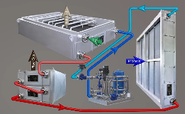
A typical Energy Recovery System comprises essential components such as an inlet recuperator (liquid to air) for process air, an outlet recuperator (air to liquid) for exhaust air, and a pump station. Depending on the drier installation design, the system may also include a flue gas recuperator for plants using an indirect gas/oil burner or flash steam/condensate recovery from the Main Steam Air Heater.
The inlet recuperator is generally installed for pre-conditioning process air or within the regeneration section of a sorption dehumidifier. The outlet recuperator is placed in the exhaust stack of the spray drier, downstream of components like cyclones, wet scrubbers,or bag filters. In setups without a recuperation system for flue gas from the indirect gas/oil main air heater, there is significant potential to recover additional energy, greatly improving overall energy efficiency. For drier installations that use steam as the heating medium, the system can be enhanced by adding a flash steam/condensate stage to further improve energy recovery, provided this feature is not already included in the heater.
The pump station plays a crucial role in circulating the heated liquid, facilitating energy transfer. This heated liquid can be repurposed for various uses beyond heating drier process air, optimizing overall factory energy utilization.
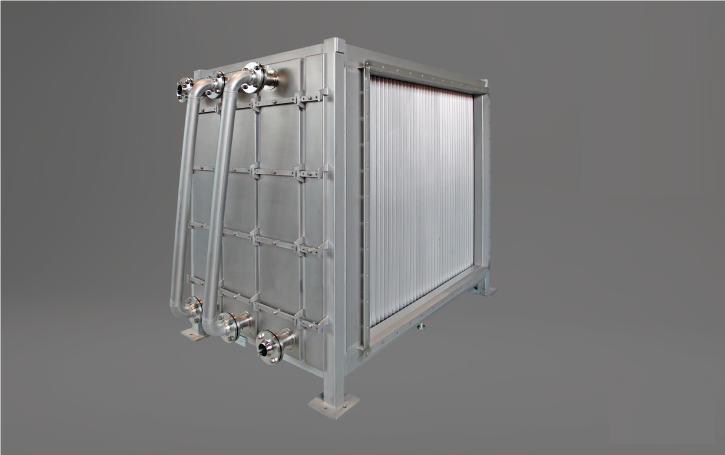
Our in-house manufactured heat exchangers are a vital component of our systems, allowing us to optimize fin spacing and length to meet specific needs. We can adjust fin pitches between 2.2 to 5.0 mm during the design phase, ensuring both effective automatic Clean-In-Place (CIP) capability and minimal system pressure drops. Our 290 mm long fins are designed to provide smooth, uninterrupted CIP liquid flow through the unit, ensuring long-term efficiency and ease of maintenance.
Optimizing Energy Recovery in Industrial Processes
Energy Recovery Systems, whether single or multi-stack, can be installed on the drier exhaust. Multi-stack systems provide the highest level of energy recovery. The advantage of a multi-stack design is its ability to utilize multiple energy sources at different temperatures, thereby improving energy distribution throughout the factory. Additionally, this system cools process exhaust air below the dew point, allowing for the recovery of latent heat through moisture condensation. Consequently, heat transfer efficiency is significantly enhanced, reducing the thermal load and the energy required for further air processing, which leads to improved overall system efficiency.
The outlet recuperator, located in the drier’s typically powder-loaden exhaust air, is equipped with an automatic CIP system that cleans the unit during the drier’s CIP process. This system includes dedicated nozzles that cover the entire heat exchanger surface, ensuring thorough cleaning. The coils feature our in-house designed fins, made from durable chrome steel (1.4016) with a thickness of 0.5 mm, allowing them to withstand pressure washing without damage.
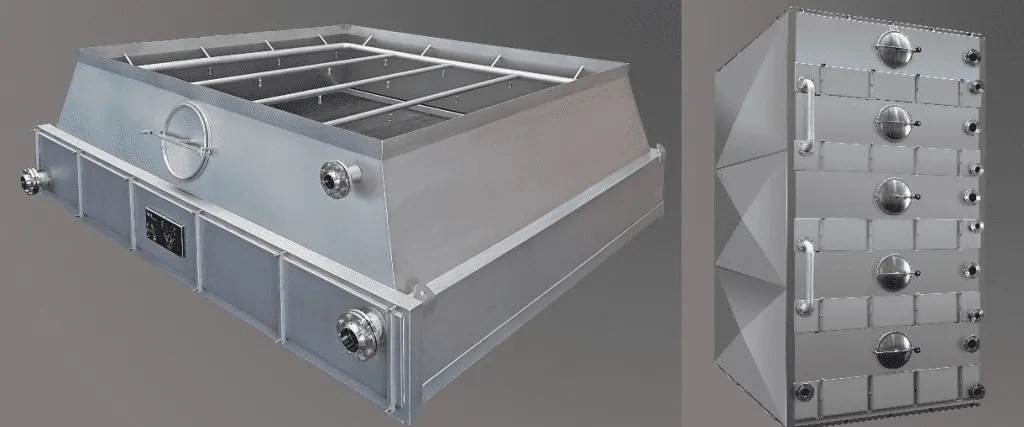
To facilitate inspection, the unit includes a manhole for easy access, and the heater section can be extracted if further inspection or cleaning is necessary. This design ensures the system remains efficient and easy to maintain over time.
Achieving short ROI with Cutting-Edge Energy
Recovery Technologies
Calculating the Return on Investment for Energy Recovery Systems
When installing an Energy Recovery System, it is important to adopt a holistic perspective, recognizing that “you invest once and benefit for years to come.” If your budget permits, opting for the more advanced solution is advisable. The cost per kW recovered decreases as system. efficiency increases, making a multi-stack system the optimal choice from an ROI standpoint. For instance, the cost of an Energy Recovery System is only 20-30% of the investment needed to achieve the same energy output from solar energy, with the added benefit of continuous energy recovery, not limited to daylight hours.
Determining the ROI period for each installation requires evaluating several critical factors:
- Cost of the energy source
- Design of the drier process (identifying the best location for the inlet recuperator(s))
- Space management (deciding if there's sufficient space inside the factory or if equipment needs to be placed outside)
- Floor load rating (ensuring the floor can bear the system's weight)
- Plant downtime for installation
- Sustainability objectives
- Other relevant considerations (e.g., maintenance needs)
There are many ways to configure an Energy Recovery System, and each choice affects energy utilization.
For the inlet recuperator, the most typical placement is as a pre-heater for the drier’s main air. However, if the drier process includes a sorption dehumidifier, the recovered energy can also be used to regenerate the sorption rotor. The remaining energy can be used to preheat the process air with an additional inlet recuperator. In some instances, no inlet recuperator is installed, and the recovered energy is used elsewhere. in the factory. In colder climates, this energy can be effectively utilized in a “winter heater” setup.
For the outlet recuperator, vertical or horizontal installations are possible. Vertical installations can be designed for either air direction, allowing for optimal integration into the process design. Horizontal installations require a higher investment due to the need for multiple CIP arrangements.
The operational hours depend on whether the exhaust system includes cyclones, a wet scrubber, or a bag filter. To optimize CIP costs, outlet recuperators are designed. to operate for multiple drier cycles. The factory’s policies determine the CIP sequence, which typically begins when the pressure drop reaches a set limit.
Expected Energy Recovery Percentages :
- Single-stack: 15-20% recovery
- Multi-stack: 40-45% recovery
With these recovery percentages, installations typically realize an ROI of under three years, and in certain instances, approximately one year. When all factors are considered, the additional cost for a new dryer installation is quite low, rendering the investment very advantageous.
Cost-Benefit Analysis of Various Energy Recovery Technologies :
Our Energy Recovery Systems are designed with fin tube heat exchanger technology, which provides unique benefits compared to alternatives such as dimple plate recuperators. While both technologies are commercially available, the fin tube heat exchanger is notable for its enhanced performance and efficiency.
Integrating Energy Recovery Systems for Optimal Savings
The next logical step involves recovering lost energy in existing dryer installations where process and product optimizations have already been fully executed. Energy Recovery Systems, despite the additional on-site work required, can significantly enhance profitability. They also support the company’s sustainability objectives by lowering CO, emissions from production.
For instance, a multi-stack system can enable a spray dryer with an exhaust air flow of 66,000 kg/h to recover over 1,000 kW per hour.
The outlet recuperator can be positioned after cyclones, a wet scrubber, or a bag filter. The system’s flexibility allows for both horizontal and vertical installations, and it can even be mounted externally on the factory roof. Recovering energy via an inlet recuperator, typically installed as a pre-section to the main air heater, is often the preferred design. Many companies consider upgrades during this installation to mitigate flash steam INDIAN DAIRYMAN or condensate energy losses, thereby further improving energy efficiency.
Long-Term Maintenance and Operation of Energy Recovery Systems
The “often overlooked features” of our Energy Recovery Systems can have a significant impact on maintenance and operation. Our design utilizes fin tube heat exchangers, where several crucial aspects are frequently neglected :
- Fin strength
- Fin mounting
- Extractability of the heater elements.
At the heart of the system is a fin that is 0.5 mm thick.
This thickness is essential as it enables the fin to endure high pressure washing without sustaining damage. The fins are mounted onto a tube to form the heat exchanger. We employ an in-house expansion technique known as “the golden ring,” which creates a stronger bond between the tube and the fin compared to traditional methods that use a steel ball for pipe expansion. The combination of a more robust fin and an enhanced mounting method results in a more durable heat exchanger.
While flanged and insulated heat exchangers are common, upgrading to a design with extractable coils provides significant advantages. The most apparent benefits include easier inspection and cleaning, but another important factor is the ability to manage damage effectively. In a standard flanged model, if a heat exchanger is damaged, it often renders the entire system non-operational. In contrast, with an extractable. version, you can remove the damaged section and continue operating at reduced capacity, thereby minimizing downtime, and keeping up production.